
What is Ultrafiltration Treatment, and How Does this Process Work?
Ultrafiltration treatment is a form of membrane filtration similar to reverse osmosis, separating solid particles from the liquid influent source. This process lies between microfiltration and nanofiltration in terms of particle capture size removal. It has applications as a prefilter for other treatment processes or as a tertiary polishing filter in drinking water and wastewater treatment applications.
How it works:
To keep it simple, ultrafiltration treatment works by using a pressure gradient to force water through a semi-permeable membrane, leaving larger particles and minerals trapped on the other side.
Of course, this membrane filter can be implemented in a variety of ways. Therefore, we will discuss and describe the different potential configurations for ultrafiltration systems.
Flow configurations:
How the influent raw water flows in relation to the orientation of the membrane can affect the operation of this system process. Each configuration has certain advantages and disadvantages that need to be considered when designing the ultrafiltration treatment system.
Outside-in
For a cylindrical membrane, raw water flows from the outer portion inward towards the central axis, as illustrated below. This flow pattern works well in higher total suspended solids (TSS) situations, as opposed to inside-out flow.
Inside-out
Influent raw water flows into the center space of a membrane tube and then radially outward, as seen below. When uniform hydrodynamics are needed, this flow pattern is best but it does not do well in higher TSS applications.
Cross-flow
The influent flows parallel to the length of the membrane, but the pressure gradient across the membrane draws the water through to the other side and solids gather on the membrane in a thin layer. More energy is required to generate cross-flow, but the layer of solids can be maintained in a thinner layer for longer.
Dead-end flow
Flow is perpendicular to the surface of the membrane. Filtered water passes through the membrane while solids remain on the opposite side, stuck to the membrane surface in a thick layer. Producing dead-end flow does not require much energy, but the solid layer builds up much faster making this configuration more useful for lower source water contaminant concentrations.
The two main considerations for how the system as a whole should be set up is based upon the vessel type and how the membranes are aerated.
Submerged
Technically, most ultrafiltration treatment systems are submerged in the sense that the membrane is completely surrounded by fluid, but in particular, this term refers to systems that are composed of large tanks filled with raw water and multiple membranes are lowered into it. The tank has the necessary inlets and outlets.
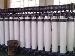
Pressurized
When a membrane is enclosed within some sort of pressurized housing unit. Systems typically consist of multiple vessels connected together in parallel. Each vessel has its own inlet and outlet that connect to a header that consolidates the treated effluent from all of the vessels into one stream. The vessels also tend to be cylindrical except in the case of a plate and frame membrane configuration.
Aeration
In order to keep membranes from gathering solids on their surface constantly, ultrafiltration units implement aeration systems that produce bubbles that scour the surface of the membrane to scrub off built up solids. There are two options for the set-up of aeration systems within the filter unit.
Integrated
In an integrated system, everything is contained within a single unit. For example, a submerged tank where the aerator is located directly beneath the membranes. Or, a pressure vessel with an aerator in the bottom of the vessel.
Separate
Here, the raw influent is aerated in a separate tank and then pumped to the tank or vessel containing the membrane.
Membrane types
Polymeric
These membranes are made of polymer materials such as polysulfone, polypropylene, cellulose acetate, and polylactic acid. Polymeric membranes are more commonly used due to their efficiency and cost-effectiveness.
Ceramic
There are a wide variety of materials for ceramic membranes, from aluminum oxide and silicon carbide to titanium dioxide and zirconium dioxide. They are well known for their resilience in the face of high temperatures or corrosive chemicals but are also much more expensive.
Membrane configurations
The size and shape of the membrane has a lot to do with how the system will operate. Each membrane configuration can have particular pros and cons, therefore, careful selection is necessary.
Tubular
Picture a bundle of straws bound together with a thin membrane rolled up inside each straw. The tubes themselves are permeable so when the influent is pumped in, it starts within the semipermeable membrane and the water passes through it, then through the tube into the vessel cavity. The resulting permeate in the cavity is then sent to the next treatment stage. Tubular systems typically only operate on inside-out flows so the membrane does not collapse within the tube.
Hollow fiber
This configuration is similar to a tubular system, but without the membrane supported inside of a tube vessel. Instead, the membrane itself looks more like hollow cooked spaghetti strands and it’s directly exposed to the raw water. These systems can be operated as inside-out or outside-in, but the thin, flexible fibers can be susceptible to breaking.
Plate and Frame
Keeping things in the kitchen, imagine this one as a club sandwich. Make a sandwich of a spacer between two flat membranes and stack multiples of those on top of one another with some space in between. The feed water travels between the adjacent membranes and filtered permeate water passes through the membranes to the spacer which has channels that carry it towards the permeate (treated) water outlet.
Spiral wound
For this one, take the sandwich you made for the plate and frame and wrap it around a perforated pipe. Raw water travels through the feed channel and filters through the membranes to the permeate channel. The permeate then spirals to the center into the outlet.
This table below indicates possible combinations for ultrafiltration treatment systems. For example, a tubular membrane configuration with inside-out cross-flow across a polymeric membrane. The X’s indicate that the flow type or membrane material is possible for the given membrane.
Membrane configuration | Outside-in | Inside-out | Cross-flow | Dead-end flow | Polymeric membrane | Ceramic membrane |
Tubular | — | X | X | X | X | X |
Hollow fiber | X | X | X | X | X | X |
Plate & frame | X | X | X | X | X | X |
Spiral wound | X | X | X | — | X | — |
Want more details on any of the information presented in this article? For questions about the ultrafiltration process or if an ultrafiltration treatment system will meet the needs of your particular application, contact us!
The water treatment experts at Genesis Water Technologies can be reached toll free in the USA at 1-877-267-3699 or you can connect with us via social media or email customersupport@genesiswatertech.com to speak with one of our representatives about your specific application.